Introduction to Pitch-Based Carbon Fibers and Braided Architectures
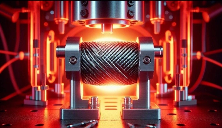
The relentless pursuit of high-performance materials for extreme aerospace, hypersonic, and advanced industrial applications has catalyzed the development of complex composite architectures capable of withstanding simultaneous thermal and mechanical extremes. At the forefront of this materials revolution are pitch-based carbon fibers. Unlike their polyacrylonitrile (PAN)-based counterparts, which are primarily celebrated for their high tensile strength, pitch-based carbon fibers are engineered to deliver unparalleled tensile modulus and extraordinary thermal conductivity. These unique properties are derived from the highly graphitic, extended-chain crystalline morphology achieved during the high-temperature processing of mesophase pitch precursors. However, the translation of these exceptional one-dimensional fiber properties into robust, three-dimensional load-bearing structures requires sophisticated textile engineering. Braided architectures, particularly two-dimensional (2D) triaxial and three-dimensional (3D) interlocking braids, offer a highly optimized geometric framework for these brittle fibers. Braiding allows for the precise orientation of continuous fiber tows, providing exceptional torsional stability, damage tolerance, and near-net-shape manufacturing capabilities. Yet, when these pitch-based braided composites are deployed in operational environments characterized by sustained high temperatures and cyclic mechanical loading, they are subjected to a complex degradation phenomenon known as thermo-mechanical fatigue (TMF), often culminating in creep rupture. Understanding the fundamental kinetics of these degradation mechanisms is absolutely critical for predicting the operational lifespan and ensuring the structural integrity of next-generation thermal and load-bearing systems.
Mesophase Pitch Precursors and Graphitization
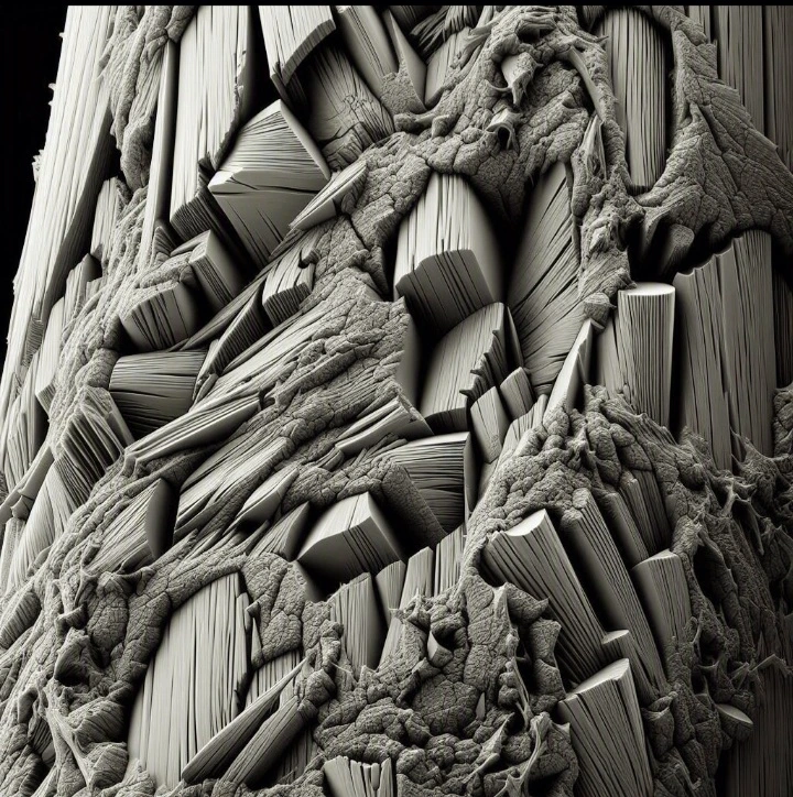
The exceptional thermomechanical properties of pitch-based carbon fibers are inextricably linked to their complex manufacturing process, which begins with the synthesis and spinning of mesophase pitch. Mesophase pitch is a liquid crystalline state of heavy aromatic hydrocarbons, typically derived from petroleum or coal tar. When heated, these discotic aromatic molecules self-assemble into highly ordered, nematic liquid crystals. During the melt-spinning process, the shear and elongational forces exerted on the fluid as it passes through the spinneret capillary align these liquid crystalline domains parallel to the fiber axis. This high degree of macromolecular orientation is kinetically frozen into the precursor fiber upon cooling. Subsequent stabilization in an oxidizing atmosphere cross-links the molecules, rendering the fiber infusible. The critical transformation, however, occurs during the carbonization and graphitization stages, where the fibers are subjected to temperatures exceeding 2500 degrees Celsius in an inert atmosphere. This extreme thermal treatment drives off non-carbon elements and induces the growth and perfection of turbostratic graphitic crystallites.
Microstructural Anisotropy and Thermal Conductivity
The resulting microstructure of a high-modulus pitch-based carbon fiber is highly anisotropic. The graphitic basal planes are extensively aligned along the longitudinal axis of the fiber, resulting in an axial tensile modulus that can approach the theoretical limit of the graphite crystal (approximately 1000 GPa). Furthermore, this highly ordered crystalline structure provides an uninterrupted pathway for phonon transport, granting pitch-based fibers an axial thermal conductivity that can surpass that of pure copper, often exceeding 800 W/m·K. However, this extreme axial performance comes at the cost of transverse properties. The weak van der Waals forces between the graphitic planes result in low transverse strength and a highly positive transverse coefficient of thermal expansion (CTE), which contrasts sharply with the slightly negative axial CTE. This profound microstructural anisotropy is the fundamental source of the complex internal stress states generated when these fibers are embedded within a composite matrix and subjected to thermal cycling.
Braided Preform Topologies in Load-Bearing Applications
To harness the stiffness and thermal conductivity of pitch-based fibers while mitigating their inherent brittleness and poor transverse properties, engineers utilize advanced braided preform topologies. In a standard 2D triaxial braid, bias yarns intertwine at specific braiding angles (typically between +/- 30 to +/- 60 degrees) while axial yarns are inserted longitudinally at zero degrees. This architecture provides a highly tailorable balance of axial stiffness and shear resistance. The continuous nature of the braided tows eliminates the discrete interlaminar boundaries found in traditional laminated composites, significantly enhancing the material’s resistance to delamination under out-of-plane impact or complex multi-axial loading.
Kinematic Confinement and Load Transfer Mechanisms
The mechanical efficacy of the braided architecture relies heavily on the kinematic confinement of the intersecting fiber tows. At the crossover points, the bias yarns undulate over and under one another, creating a localized crimp. When a tensile load is applied to the composite, these crimped yarns attempt to straighten, generating severe transverse compressive forces at the nodal intersections. This kinematic confinement enhances the frictional load transfer between the tows and the surrounding polymer or ceramic matrix. However, the crimp also introduces localized stress concentrations and bending moments into the brittle pitch-based fibers. Under static loading, these stress concentrations can initiate premature fiber fracture. Under dynamic thermo-mechanical loading, the undulating geometry of the braid dictates the complex pathways of fatigue crack propagation and the localized accumulation of creep strain.
Thermo-Mechanical Fatigue (TMF) in Braided Composites
Thermo-mechanical fatigue (TMF) represents one of the most severe operational conditions for any structural material. It involves the simultaneous application of cyclic mechanical loading and cyclic thermal loading. In aerospace applications, such as exhaust nozzles or leading-edge structures, these cycles are often inextricably linked; an increase in aerodynamic load is typically accompanied by a spike in aerodynamic heating. The degradation kinetics under TMF are fundamentally different from, and often far more aggressive than, the sum of isothermal mechanical fatigue and stress-free thermal cycling.
Cyclic Thermal Loading and Internal Stress Generation
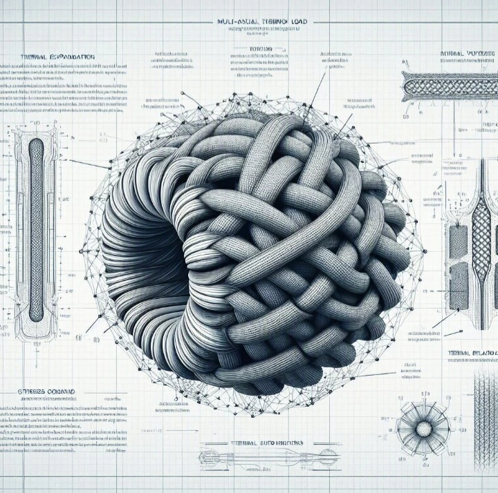
The primary driver of degradation during TMF is the continuous generation and fluctuation of internal residual stresses. A braided composite is a heterogeneous system comprising the highly anisotropic pitch-based carbon fibers and an isotropic matrix (typically a high-temperature polyimide, bismaleimide, or a ceramic matrix like silicon carbide). As the ambient temperature fluctuates, these constituent phases attempt to expand and contract at vastly different rates.
Coefficient of Thermal Expansion (CTE) Mismatch
The CTE mismatch between the pitch-based fibers and the matrix is extreme. As previously established, the axial CTE of the carbon fiber is negative, meaning it contracts upon heating, while its transverse CTE is highly positive. Conversely, a typical polymer matrix possesses a high, isotropic positive CTE. During the heating phase of a TMF cycle, the matrix attempts to expand volumetrically. The carbon fibers resist this expansion longitudinally but expand radially against the matrix. This generates massive interfacial shear stresses along the length of the fiber and severe radial compressive stresses. During the cooling phase, the matrix attempts to shrink around the fibers, generating radial tensile stresses that actively attempt to pull the matrix away from the fiber surface. When this cyclic thermal stress is superimposed upon a cyclic mechanical load, the resulting multi-axial stress state at the fiber-matrix interface rapidly exceeds the fatigue limit of the constituent materials.
Fatigue Crack Nucleation and Propagation
The accumulation of damage during TMF in pitch-based braided composites follows a distinct, progressive sequence. The continuous fluctuation of the interfacial shear stresses, exacerbated by the geometric stress concentrations at the braided crossover points, leads to the rapid nucleation of microstructural defects.
Interfacial Shear Stress and Fiber-Matrix Debonding
The degradation initiates with the breakdown of the fiber-matrix interface. The cyclic shear stresses cause the chemical and mechanical bonds between the fiber sizing and the matrix to yield and eventually rupture, a process known as debonding. Once debonding occurs, the efficiency of load transfer from the matrix to the load-bearing fibers is severely compromised. Following debonding, the unconstrained matrix is subjected to elevated localized strains, leading to the nucleation of transverse matrix micro-cracks. In a braided architecture, these matrix cracks typically initiate in the resin-rich pockets between the undulating tows and propagate along the fiber-matrix interfaces. As the TMF cycling continues, these micro-cracks coalesce, forming macroscopic damage networks that drastically reduce the global stiffness of the composite. The following list delineates the primary modes of fatigue damage observed in these advanced architectures:
- Interfacial Debonding: The primary failure of the chemical and mechanical adhesion between the pitch-based carbon fiber and the surrounding matrix due to cyclic CTE mismatch shear stresses.
- Transverse Matrix Cracking: The nucleation and propagation of cracks within the polymer or ceramic matrix, typically initiating at the resin-rich interstitial voids of the braided preform.
- Tow-to-Tow Friction and Wear: The internal abrasion of intersecting bias yarns at the braided crossover points, exacerbated by the loss of matrix support and the straightening of the crimped tows under load.
- Fiber Fracture: The ultimate brittle failure of the individual pitch-based carbon filaments, driven by localized bending stresses at the braid nodes and the transfer of excessive load from the degraded matrix.
- Oxidative Degradation: The accelerated chemical breakdown of the carbon fibers and the polymer matrix at elevated temperatures, facilitated by the ingress of atmospheric oxygen through the interconnected network of fatigue cracks.
Creep Rupture Kinetics at Elevated Temperatures
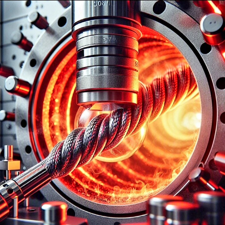
While TMF addresses cyclic loading, many high-temperature applications subject the braided composite to sustained, static tensile loads over extended periods. Under these conditions, the material undergoes creep— a time-dependent, irreversible plastic deformation. If the sustained load and temperature are maintained, this creep deformation will eventually culminate in creep rupture, a catastrophic structural failure.
Viscoelasticity and Matrix Degradation
In polymer matrix composites (PMCs), the creep behavior is heavily dominated by the viscoelastic nature of the matrix. As the operational temperature approaches the glass transition temperature (Tg) of the polymer, the macromolecular chains gain sufficient thermal energy to overcome secondary intermolecular bonds. Under a sustained tensile load, these chains begin to uncoil, slide, and flow. This viscoelastic flow causes the matrix to shed its portion of the applied load, transferring it entirely to the reinforcing carbon fibers.
Time-Temperature Superposition Principle
The kinetics of this matrix-dominated creep can be mathematically modeled using the Time-Temperature Superposition (TTS) principle. TTS posits that the viscoelastic behavior of a polymer at high temperatures over a short duration is equivalent to its behavior at lower temperatures over a much longer duration. By generating short-term creep data at various elevated temperatures and applying specific shift factors (often derived from the Williams-Landel-Ferry or Arrhenius equations), engineers can construct a master curve that predicts the long-term creep compliance of the composite matrix over decades of operational life. However, in pitch-based braided composites, the matrix creep is only the first stage of the rupture process.
Fiber-Dominated Creep and Delayed Rupture
It is a common misconception that carbon fibers do not creep. While PAN-based fibers exhibit negligible creep at temperatures below 1000 degrees Celsius, ultra-high-modulus pitch-based carbon fibers, due to their highly graphitic and ordered structure, can exhibit measurable creep at significantly lower temperatures when subjected to high sustained stresses. The creep mechanism in these highly crystalline fibers involves the slow, stress-activated sliding of the graphitic basal planes past one another, mediated by the movement of crystalline dislocations and point defects.
Weibull Statistical Analysis of Fiber Failure
As the matrix creeps and transfers stress to the fibers, the individual pitch-based filaments are subjected to increasing axial loads. Because ceramic and carbon fibers are inherently brittle, their ultimate tensile strength is not a single deterministic value, but rather a statistical distribution governed by the presence of microscopic surface and internal flaws. The probability of fiber failure under sustained load is modeled using Weibull statistics. As the internal stress on the fiber bundle increases due to matrix relaxation, the fibers with the most severe flaws rupture first. When a fiber breaks, its load is dynamically redistributed to the surviving adjacent fibers, increasing their probability of failure. This creates a cascading effect. Creep rupture occurs when a critical cluster of broken fibers forms, and the remaining intact fibers can no longer sustain the applied macroscopic load. The following table illustrates the comparative thermomechanical properties and creep characteristics of pitch-based versus PAN-based carbon fibers when embedded in a high-temperature polyimide matrix.
| Fiber Type / Precursor | Axial Tensile Modulus (GPa) | Axial Thermal Conductivity (W/m·K) | Creep Rupture Threshold (1000h at 300°C) | Primary High-Temp Failure Mechanism |
|---|---|---|---|---|
| Pitch-Based (Ultra-High Modulus) | 800 – 950 | 500 – 850 | 65% of Ultimate Tensile Strength | Basal plane sliding and delayed brittle fracture |
| PAN-Based (High Strength) | 230 – 290 | 10 – 20 | 85% of Ultimate Tensile Strength | Matrix-dominated shear failure and oxidation |
| Pitch-Based (High Thermal) | 600 – 750 | 900 – 1100 | 60% of Ultimate Tensile Strength | Severe CTE mismatch debonding and fiber pull-out |
Empirical Testing and Computational Modeling
The rigorous characterization of TMF and creep rupture kinetics requires a synergistic approach, combining highly specialized empirical testing protocols with advanced computational modeling. This dual methodology ensures that the theoretical degradation models accurately reflect the physical reality of the braided composite’s response to extreme environments.
High-Temperature Creep and Fatigue Testing Protocols
Empirical testing of these advanced materials necessitates the use of servo-hydraulic testing frames equipped with precision environmental chambers or induction heating systems capable of maintaining stable temperatures exceeding 400 degrees Celsius for polymer matrices, and up to 1500 degrees Celsius for ceramic matrix composites. The following procedural list outlines the standardized methodology for conducting high-fidelity thermo-mechanical creep rupture testing on braided composite specimens:
- Specimen Preparation and Machining: Fabricate the pitch-based braided composite panels using a vacuum-assisted resin transfer molding (VARTM) process. Precision-machine the panels into standard rectangular or dog-bone coupons, ensuring the braided unit cells are symmetrically aligned with the loading axis to prevent induced bending moments.
- High-Temperature Extensometry Integration: Affix specialized, water-cooled high-temperature extensometers or utilize non-contact laser/optical Digital Image Correlation (DIC) systems to continuously monitor the axial and transverse strain of the specimen within the heated gauge section.
- Thermal Equilibration: Mount the specimen in the testing frame and elevate the environmental chamber to the target isothermal setpoint. Maintain this temperature for a minimum of two hours prior to load application to ensure complete thermal equilibrium and the stabilization of initial CTE-induced stresses.
- Sustained Load Application: Apply the target static tensile load smoothly to avoid dynamic shock. The load is typically calculated as a specific percentage of the material’s ultimate tensile strength at that specific elevated temperature.
- Continuous Data Acquisition: Continuously log the strain, load, and temperature data at a high sampling rate to capture the primary (transient), secondary (steady-state), and tertiary (accelerated) phases of the creep curve.
- Acoustic Emission Monitoring: Utilize high-frequency acoustic emission sensors attached to the cool ends of the specimen to detect and record the transient elastic waves generated by internal micro-cracking and individual fiber ruptures, providing real-time data on damage accumulation.
- Post-Rupture Fractography: Upon catastrophic failure, carefully extract the fracture surfaces and subject them to Scanning Electron Microscopy (SEM) to determine the dominant failure modes, such as matrix yielding, interfacial debonding, or brittle fiber pull-out.
Finite Element Analysis (FEA) of Braided Unit Cells
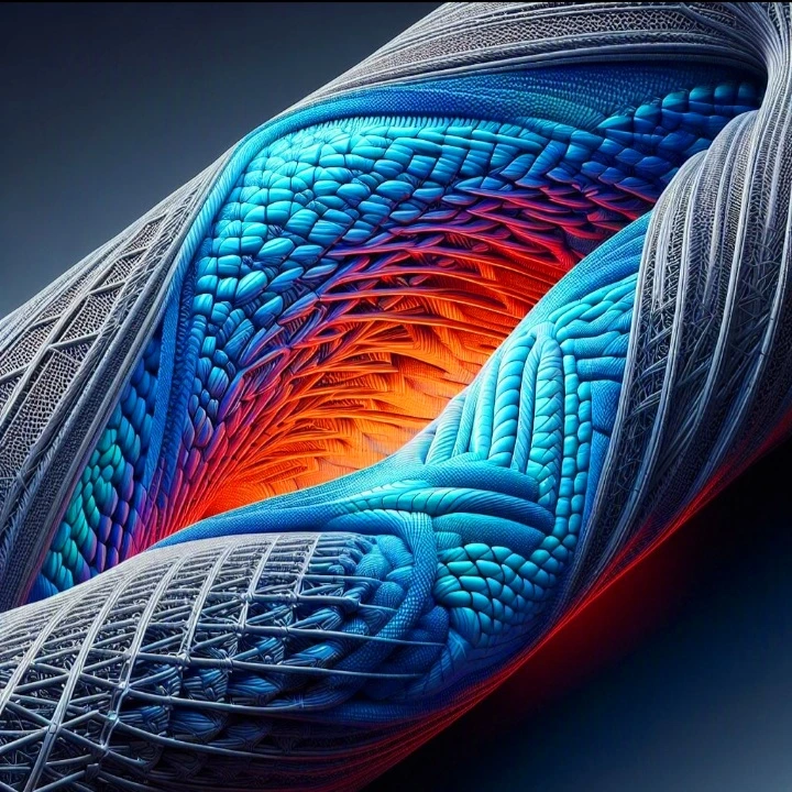
While empirical testing provides macroscopic failure data, Finite Element Analysis (FEA) is indispensable for visualizing and quantifying the localized stress concentrations and damage evolution within the complex braided architecture. Due to the computational expense of modeling an entire macroscopic component, FEA is typically applied to a Representative Volume Element (RVE) or a single braided unit cell.
Constitutive Modeling and Damage Mechanics
The FEA models must incorporate advanced constitutive equations that account for the anisotropic thermo-elastic properties of the pitch-based fibers and the temperature-dependent viscoelasticity of the polymer matrix. To simulate TMF and creep rupture, Continuum Damage Mechanics (CDM) frameworks are integrated into the solver. These frameworks utilize damage state variables that progressively degrade the stiffness matrix of the elements based on specific failure criteria, such as the Hashin or Puck criteria for fiber and matrix failure, and cohesive zone models (CZM) to simulate the progressive debonding of the fiber-matrix interface. The following table outlines the critical material parameters and boundary conditions required for a high-fidelity FEA simulation of a braided unit cell under thermo-mechanical loading.
| FEA Parameter Category | Specific Input Variables | Constitutive Model / Application |
|---|---|---|
| Fiber Properties (Pitch-Based) | Axial/Transverse Modulus, Poisson’s Ratio, Axial/Transverse CTE, Thermal Conductivity | Transversely Isotropic Thermo-Elastic Model |
| Matrix Properties (Polyimide) | Temperature-Dependent Modulus, Glass Transition Temp (Tg), Viscoelastic Prony Series | Generalized Maxwell Viscoelastic Model with Thermal Shift Factors |
| Interfacial Properties | Interfacial Shear Strength (IFSS), Mode I/II Fracture Toughness, Traction-Separation Law | Cohesive Zone Modeling (CZM) for progressive debonding simulation |
| Boundary Conditions | Periodic Boundary Conditions (PBCs), Cyclic Thermal Gradients, Multi-Axial Stress Tensors | Ensures kinematic continuity of the RVE during simulated macroscopic deformation |
Advanced Applications and Future Trajectories
The rigorous characterization of thermo-mechanical fatigue and creep rupture kinetics in pitch-based carbon fiber braids is not merely an academic exercise; it is a critical prerequisite for the advancement of next-generation aerospace and industrial technologies. The unique combination of ultra-high stiffness, exceptional thermal conductivity, and the damage tolerance of the braided architecture makes these composites highly sought after for the most demanding operational environments.
Aerospace and Hypersonic Implementations
In the realm of hypersonic flight, vehicles traveling in excess of Mach 5 experience extreme aerodynamic heating, with leading-edge temperatures rapidly exceeding 1000 degrees Celsius. Traditional metallic alloys lose their structural integrity at these temperatures, and conventional PAN-based composites lack the thermal conductivity to efficiently dissipate the localized heat flux. Pitch-based braided composites, particularly when integrated with ceramic matrices (such as Silicon Carbide, forming C/SiC composites), offer a revolutionary solution. The high thermal conductivity of the pitch fibers acts as an active thermal management system, rapidly conducting heat away from the stagnation points and distributing it across the broader structure, thereby preventing localized thermal ablation. The braided architecture ensures that even if the brittle ceramic matrix micro-cracks under the severe thermal shock, the continuous interlocking fibers will bridge the cracks, preventing catastrophic structural failure and maintaining the aerodynamic profile of the vehicle.
Next-Generation Matrix Formulations
The future trajectory of this technology relies heavily on the continuous optimization of the matrix materials and the fiber-matrix interphase. To mitigate the severe degradation caused by CTE mismatch, researchers are developing advanced nanocomposite matrices. By doping high-temperature polyimides or pre-ceramic polymers with functionalized graphene oxide or boron nitride nanotubes, engineers can tailor the bulk CTE of the matrix to more closely match that of the transverse carbon fibers, drastically reducing the internal residual stresses generated during thermal cycling. Furthermore, the development of advanced, oxidation-resistant sizing agents for the pitch-based fibers will enhance the interfacial shear strength and protect the carbon filaments from environmental degradation at extreme temperatures. Ultimately, the mastery of these complex thermo-mechanical kinetics will enable the design of ultra-lightweight, hyper-resilient structural components that push the boundaries of speed, efficiency, and durability in the aerospace and advanced energy sectors.